High Pressure Breathing Air Compressor Filtration System Design
author:- Stephen E Burton BSc(hons) C.Eng, MIET – Email to:- scubaengineer@gmail.com
Introduction
Many homes and small workshops have single stage compressors capable of producing 7bar/100psi pressure for powering hand tools and filling truck tires. These simple compressors use the most basic engineering techniques and are successfully mass produced out in the Far East as a low cost consumer product.
It comes as quite a surprise when a dive operation comes to purchase their first high pressure divers breathing air compressor to be met with a price tag approaching that of a family car, and the use of which is surrounded by a pile of legal regulations and maintenance obligations, and competent operator requirements which if not met, will cause several well known phenomena:-
-
The compressor may explode – blowing the operator and the dive center to bits
-
The compressor will overheat and pump highly poisonous carbon monoxide laced air
-
The compressor will pump wet air leading to the early failure of every cylinder filled by it.
Thankfully, explosions and poisonous air (cases 1 & 2 above) are relatively uncommon, and may be easily prevented by routine long-term maintenance and correct positioning in a well ventilated position away from petrol and diesel engine exhaust fumes.
However, recent Government divers breathing air testing results (#1,7) and feedback from compressor maintenance technicians confirms that “75% of all divers breathing air compressors are pumping air that fails to meet the moisture content requirements of EN12021”.
Since all modern divers breathing air compressors are designed to produce clean dry divers breathing air in accordance with EN12021, the non compliant air can only be caused by one of the following faults:-
-
The condensate drains are not being vented often enough (typically every 15 minutes)
-
The final output filter is not being changed often enough (The change interval varies considerably dependent on the compressor pumping rate, the filter size, and the ambient operating temperature)
-
Incorrect adjustment of the final Pressure Maintaining Valve (PMV)
It is the operation and adjustment of the last item ‘The PMV’ that causes the most puzzlement amongst compressor users, and is the most commonly overlooked routine compressor adjustment.
High Pressure Divers Breathing Air Compressor operators… Ignore the PMV at your peril !!! – since the correct functioning of this simple mechanical valve removes more than 99% of all moisture present in the final compressed air; If the PMV does not work, the high levels of humidity still present in the air reaching the final filter tower will trash the expensive air filter cartridge before you have even filled the first cylinder, and condemn to early failure at annual visual inspection every subsequent SCUBA cylinder filled by it, due to high levels of internal corrosion.
Talking to dive center owners and compressor operators reveals a complete misunderstanding about the basic operation of the specialist filtration system characteristic of all high pressure divers breathing air compressors.
What this article attempts to do is to expose the commonly held misconceptions about how compressor filtrations systems work, and to underline the essential checks and maintenance necessary to produce clean dry divers breathing air – and save the dive operator a pile of money long-term in unnecessary scuba tank replacement costs.
The Multi-stage High Pressure divers breathing air compressor – an introduction
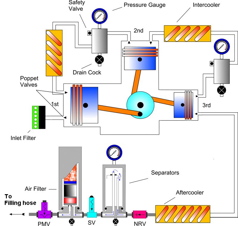 This picture courtesy of:- Mr. Stuart Meinert , author of the Dive Technician Training Course
Key:- NRV = Non Return Valve – a one way valve SV = Safety valve. The final safety valve is usually set 10% above the cylinder maximum working pressure PMV = Pressure maintaining valve – A crucial part of the filtration system usually set to release pressure between 120-160 bars.
After a bit of bug filtration and three stages of compression each delivering up to x7 multiplication in pressure, most modern high pressure divers breathing air compressors can deliver air potentially 7x7x7= 343bars/5,000psi. Typically, several internal safety valves limit the pressure generated to safe limits tolerated by both the compressor mechanical parts, and the scuba tank to be filled.
Following the last compression stage, the air passes through the final Air Filter whereupon it emerges ready to pass through the filing hose into the divers scuba tank.
The air should then meet international standards for divers breathing quality air, which basically state that the air should be clean, dry, free from odor, and containing extremely low levels of poisonous contaminants such as oil, carbon dioxide, and carbon monoxide.
For this article, we’ll look at how a high pressure divers breathing air compressor filtration system is designed to meet a typical modern air purity standard such as EN12021, how this determines the compressor filter size, the condensate purge interval times, the pressure maintaining valve setting, Molecular sieve mass, Activated Carbon mass, and the influence of all these parameters on predicting the filter lifetime over a range of operating temperatures and humidity levels. First lets have a look at the air standard we’d like to meet or exceed.
Divers Breathing Air Purity Standard EN12021
- Oxygen 20-23%
- Carbon Dioxide Less <500ppm
- Oil <0.5mg/m^3
- Carbon Monoxide <15ppm
- Water Vapor <50mg/m^3 for 40-200bars
- Water Liquid <No free water.
- Odor & Taste Freedom from both
- Particles None(not defined)
Why use EN12021? This air purity standard was chosen so as include essential test criteria for water vapor content and lower oil levels associated with odorless breathing gases that were missing from older divers breathing air test standards such as the US-Navy (#2), & even the current CGA G-7.1 Grade “E” that are known to permit the production curiously smelling (though ‘not objectionable’) breathing air, and progressive internal tank corrosion through high un-monitored moisture levels.
The compression process starts here!
The air entering the compressor has the following ‘typical’ ISO 2533 parameters
- Nitrogen (N 2 ) 78.084%
- Oxygen (O 2 ) 20.946%
- Argon (Ar) 0.934%
- Carbon Dioxide (CO 2 ) 0.033%
The remaining typically 0.003%(30ppm) consists of • a mix of Neon, • Helium, • Krypton, • Xenon, • Radon, • Hydrogen and• Carbon Monoxide Background Carbon Monoxide
Concerns These typical ISO 2533 air parameters listed above, would be realised in an open green fields site, far away from any large industrial city. However, air tested in a city centre, or near a large airport could easily exceed these parameters especially for poisonous trace gases such as carbon monoxide. Such a polluted location would require the use of a Hopcalite after filter to catalyze the highly toxic carbon monoxide into the more tolerated gas carbon dioxide, even when the cylinder is filled using a perfect compressor system.
Background Carbon Dioxide Concerns

Increasing pollution and rising world carbon dioxide levels associated with global warming, are expected to cause the background carbon dioxide level to exceed the acceptable 500ppm level for divers breathing quality air within the next 50 years, indicating a future requirement to use carbon-dioxide scrubber pre-filters on all divers breathing air compressors(#4)
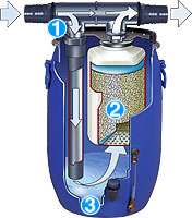
Bauer Aeroguard Carbon dioxide removal pre-scrubber system – approx filter life 50hours depending on compressor F.A.D. and size of Aeroguard unit chosen. Note #1 that only 2/3rd of the intake air goes through the Scrubber chemicals. Note #2 that the air is bubbled through water to establish a high enough humidity for the Scrubber chemicals to work effectively.
This picture and data courtesy of Bauer Kompressoren, Munchen, Germany http://www.bauer-kompressoren.de
But what about the air’s water content?
Air at different temperatures contains widely varying amounts of moisture content. Hot 100% humid air at the 45 degrees ‘C’ maximum compressor operating temperature often quoted, contains more than 10 times as much air than cold air near freezing point 0 degrees ‘C’
100% RH air at 45 degrees ‘C’ contains 65.5g/m^3 water 100% RH air at 0 degrees ‘C’ contains 4.85g/m^3 water
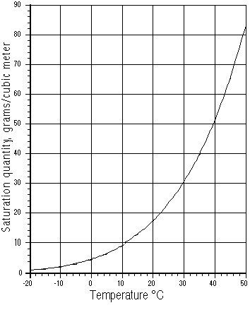
Fig 1 – Humidity Content graph of air at 100% RH versus temperature in degrees ‘C’
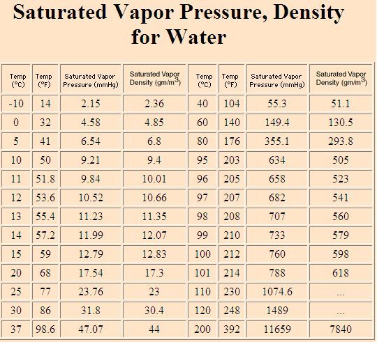 graph courtesy of http://hyperphysics.phy-astr.gsu.edu/HBASE/Kinetic/watvap.html#c1 Fig 2 – Humidity Content table of air at 100% RH versus temperature in degrees ‘C’
The compressor critical final filtration system consisting of Molecular Sieve (MS), Activated Carbon (AC) and Hopcalite (HC) elements, can only operate in the presence of truly tiny amounts of moisture. The bulk of the moisture present in the air entering the compressor MUST be removed by the high pressure compressor system design prior to the smelly, oily, moist high pressure air hits the final air filter cartridge for final ‘trace level’ filtration’.
 ….and here lies the big misunderstanding:-
Question: How is the 99.3% of all water removed from the compressor air? Answer: By the Compressor Pressure Maintaining Valve (PMV) located after the Main MS/AC air filter!
An adjustable Pressure Maintaining Valve PMV fitted to all Divers breathing air compressors This picture courtesy of Bauer Kompressoren, Munchen, Germany http://www.bauer-kompressoren.de
The huge amounts of water removed by the compressor condensate system become rapidly apparent to anyone who has ever operated a correctly adjusted high pressure compressor in the tropics.
To fill only one standard aluminum DOT-3AL3000 80cuft (207bar/11Liter) scuba cylinder with divers breathing quality air at 35 degrees ‘C’ ambient (leading to a final filter tower of typically 45 degrees ‘C’) will require the compressor condensate system to remove (11 x 207 x 65.5)/1000 = 149cc of water, shown below
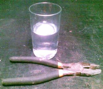 Fig 3 – Water contained in the humid 45 degrees ‘C’ air used to pump just one 207bar/3,000psi scuba cylinder
To remove 99.3% of the water present in the air, the compressor MUST have a PMV, and it must be set to at least 140bars/2,000psi.
The final filtration cartridge only removes the final minute traces of moisture remaining that are not removed by compression to the PMV release pressure.
Needless to say, the compressor interstage condensate towers must be large enough to hold all the water being collected after each compressor stage over the full operating temperature range, ambient humidity levels, and at the manufacturers published ‘purge’ times ranging from 5-30mins.
Due to the misunderstanding that exists about how divers breathing air compressors work, it is surprising that not all of these compressors even have a PMV, or have interstage condensate traps of sufficient volume to collect all the water condensed. Such compressors cannot possibly produce EN12021 Divers breathing quality air over the published life of the filter cartridge, regardless of marketing claims!
How does the PMV remove 99.3% of the water? This process is easy to visualize if you think of a typical fully water saturated bathroom sponge. If you squeeze the sponge into a shape half it’s original volume, then half the water in the sponge will be forced out. If you squeeze it into 1 quarter of the original volume, 3/4 of all the water will be forced out.
When compressing air to 140bars, you squeeze out (1- 139/140) of all the water present. Thus only 1/140 of the original water will remain = 0.7% approx.
Question: After compressing to 140bars and removal of 99.3% of all the water in the air, is the air now dry enough to pass EN12021 humidity standards? Answer: Sadly NOT. It isn’t even anywhere near the required dryness standard!
Consider; Air at 45 degrees ‘C’ has 65.5g/m^3 (66.5cc of water per cubic meter) By compressing this air to 140 bars, we will still have 66.5/140 = 0.475g/m^3 of water remaining. Which comparing with the EN12021 limits of 50mg = 0.050g/m^3 reveals that unfiltered 140bar compressed air has a massive 10 times the required EN12021 limit.
To remove this final 0.476g/m^3 of water from the already high pressure air can now only be using two techniques:-
- Chilling the high pressure air to close to 0 degrees ‘C’ so as to cause condensation of moisture in the high pressure air. This is a very effective technique used in industrial high pressure driers, but is rarely used in small dive center compressor systems
- By the use of a water absorbent chemicals such as molecular sieve, activated alumina, or silica gel.
In this instance, lets use molecular sieve as the moisture absorbent for this remaining 0.7% of water present in the original air.
It is important to understand that all of these absorbent chemicals have only a small finite absorbency capacity. In the case of molecular sieve, it is only able to absorb up to 20% of it’s ‘brand new’ dry weight as water vapor.
So knowing the operating temperature, PMV pressure setting, and weight of the molecular sieve used in the compressor filter output filter, it is possible to accurately predict the life of the filter.
As an exercise, Lets consider the following two examples of leading manufacturers compressors being used in tropical conditions of 35degrees ambient, leading to a 45 degrees ‘C’ final filter tower temperature. The Industry standard Bauer Mariner 250, and Coltrisub MCH16 divers breathing air compressors.
It should be added that the conditions used for these calculations are entirely representative of the ambient conditions found at most holiday dive shop operations found in popular dive travel destinations in tropical locations, and are by no way extreme.
Lets find out how long the MS in the filter cartridges will last in these tropical conditions…
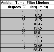 Bauer Mariner 250, with P31 filter system
MS=300g, AC=40g. Pumping rate 250L/min 35 degree ambient, 45 degree ‘C’ final filter tower temperature. From this, the MS filter bed can absorb a maximum 20% of 300g = 60g of water Thus the MS filter bed can process 60/0.475 = 126.3 m^3 of air Now, since the compressor pumps 0.250m^3/min, the MS in the filter will last 126.3/0.250 minutes = 505.2min = 8hrs 25.2mins
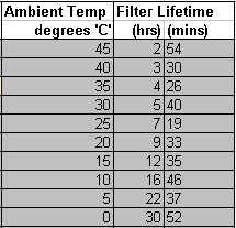 Coltrisub MCH16, with standard filter cartridge system
MS=168g, AC=50g, Pumping rate 266L/min 35 degree ambient, 45 degree ‘C’ final filter tower temperature From this, the MS filter bed can absorb a maximum 20% of 168g = 33.6g of water Thus the MS filter bed can process 33.6/0.475 = 70.7m^3 of air Now, since the compressor pumps 0.266m^3/min, the MS in the filter will last 70.7/.266 minutes = 265.8min = 4hrs 25.8mins
- Math Notes & Calculation spreadsheets:- Both compressors have the final output filter tower placed in the warm airflow coming off the 100degree C cylinder heads Empirical measurements reveal that the filter tower temperature is approx 10-14 degrees C above ambient (Ref #8) It is the actual filter tower temperature that determines the moisture that needs to be removed by the filter and thus determines the cartridge life (not the ambient temperature)
- Filter Math realization spreadsheet – Used to generate these results:- compressor_filter_lifetime_calculator.xls
Example PMV Adjustment Instructions
 Bauer PMV 150 +/- 10bars Bauer PMV 150 +/- 10bars |
 Coltrisub PMV 120-150bars Coltrisub PMV 120-150bars |
But this is only half the story – What about oily smells?
Having a good feel now for how the PMV and molecular sieve work together to produce EN12021 ‘bone dry’ high pressure divers breathing air. How do we remove the oily smell?
We must use a second common chemical Activated Carbon (AC) to remove oily smells. But the air must be perfectly dry before it gets to the AC, or it won’t remove the oily smell efficiently.
How much oil is in unfiltered compressed air? Complicated measurements involving gas spectrometers by compressor oil manufacturers (#5) have revealed the following oil content in compressed air measured at the typical cylinder head temperature of 100 degrees ‘C’
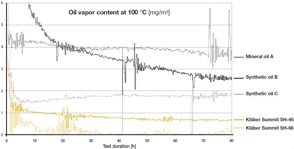 Fig 4. Above graph courtesy of www.klueber.com – Manufacturer of specialist oils for use in high pressure compressors featuring extremely long life (8,000hrs) and extremely low evaporation rates.
It can be seen that once ‘run in’, most compressors using oil lubrication are able to achieve better than 5mg/m^3 oil level in the outlet air stream. It is seen that mineral oils evaporate many times more than modern synthetic types leading to smelly air, greater oil consumption, and likely quicker saturation of the AC filter bed. From the above chart it is easy to see why the old US Navy divers breathing air standard used 5mg/m^3 – It was since most high pressure compressors lubricated by oil could readily achieve it! However, 5mg/m^3 is 10 times the current EN12021 limit of only 0.5mg/m^3. Non of the oils above will be able to achieve this level of oil mist in the compressor output air without additional Activated Carbon filtering, which brings us nicely to the next question:-
Question: How much Activated Carbon mass does the compressor air filter need? Answer: Just as for the molecular sieve, it depends on the pumping rate, ambient temperature, and if you want to squeeze the maximum life out the activated carbon, then from the above graph it plainly depends on what oil you are using!
However, compressor output filter cartridges are currently not specified for use only with one particular oil – and thus it is safe to assume that the activated carbon life is based on typical maximum oil mist levels of 5mg/m^3. So we will use a 5mg/m^3 oil mist level, as the target amount to be removed by the Activated Carbon during our generic oil absorbency calculations. This covers all oils given in Fig 4.
Lets find out how long the AC in the filter cartridges will last… Activated Carbon is typically quoted as being able to absorb 5-10% of a typical oil, so for our calculation purposes, we will assume that the activated carbon used can absorb up to a median 7.5% of it’s weight in oil.
Bauer Mariner 250, P31 filter system. MS=300g, AC=40g. Pumping rate 250L/min, 100 degree ‘C’ cylinder head temperature From this, the AC filter bed can absorb a maximum 7.5% of 40g = 3g of oil Thus the AC filter bed can process 3/0.005 = 600m^3 of air Now, since the compressor pumps 0.250m^3/min, the AC bed in the filter will last 600/.250 minutes = 2400min = 40hours 0mins
Coltrisub MCH16, standard filter system, MS=168g, AC=50g, Pumping rate 266L/min, 100 degree ‘C’ cylinder head temperature From this, the AC filter bed can absorb a maximum 7.5% of 50g = 3.75g of oil Thus the AC filter bed can process 3.75/0.005 = 750m^3 of air Now, since the compressor pumps 0.266m^3/min, the AC bed in the filter will last 750/.266 minutes = 2819min = 47hrs 0mins
Brilliant, we are nearly there and can comprehend the following:-
- We understand that it is the PMV alone that removes 99.3% of all water from the divers breathing air
- Without a working PMV, the MS and AC beds in the expensive final output filter will be likely trashed by uncondensed water before the first tank is pumped.
- That the life of MS in the final output filter is dependent on the ambient temperature, and specifically on the final air filter tower temperature
- That the life of the AC in the final output filter is actually dependent on the rate of evaporation of the compressor oil used, and that this occurs most readily in the high temperatures achieved in the cylinder head, and that to predict the filter life that is valid for all popular compressor oil types, an incoming oil mist concentration of 5mg/m^3 must be used.
Which leaves only a couple of final question concerning the ‘maximum gas flow rate in L/min the filter can handle’…
Question:- How big does the filter physically need to be, and does it have a maximum flow rate limit? Answer:- Depends on the compressor pumping rate, the cross section of the filter, and the required ‘dwell time’ for the filter media used.
As difficult as it has been to find published parameters for all other tech data presented in this paper, I have been unable to find any published dwell time data for either the MS or AC filter media – let alone, dwell time data given for different temperatures and pressures
However, similar gas absorbent chemicals such as rebreather scrubber chemicals that remove carbon dioxide, generally work on a 2 second dwell time as the minimum required time for the gas to pass through the filter bed so as to remove 95% of the contaminant chemical.
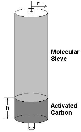
Activated Carbon Volume= pi x r^2 x h
r & h in [cm]
PMV pressure in bars
Dwell time in seconds ( assumed =2)
Filter max flow rate (at pressure) in liters/minute is:-
pi x r^2 x h x (60/dwell-time) x PMV / 1000
The Bauer P31 filter, r=3.5cm, h=4cm. This gives an estimated max flow rate = 647Liter/minute The Coltrisub MCH16 cartridge, r=2cm, h=7.5cm. This gives a max flow rate = 394Liter/minute
Both the Bauer & the Coltrisub filter dimensions and bed sizes adequately meeting their 250L & 266L/min pumping rates respectively.
- Filter Math realization spreadsheet – Used to generate these results:- compressor_filter_lifetime_calculator.xls
Removing Carbon Monoxide
This is the final ‘Black art’ with no published information anywhere for the design of the various catalytic converters to remove carbon Monoxide from Divers breathing air at high pressure.
All reputable breathing divers air compressor manufacturers have filter cartridges available that include a Hopcalite catalyser for Carbon Monoxide removal.
My research has revealed only the following information:-
The Current practice is to use 1g or Hopcalite per 5Liter/min of compressor flow rate
This Hopcalite quantity has been found to guarantee the ability of the compressor to accept an input air impurity level up to only 25ppm Carbon Monoxide and produce compressed air of up to 330bar with less than 5ppm Carbon Monoxide content (The old BS4275 breathing air standard)
 Carbon Monoxide removal capabilities of compressor filters and Notes on Carbon dioxide impurities caused by having too many workers in the compressor room (Click thumbnail for HIRES image)
This filtration requirement is likely to allow the compressor to be used in a typical polluted European or American inner city dive center, and yet still be able to produce high pressure divers breathing air fills that meets all international air purity standards.
Note that this quantity of Hopcalite It is not enough to remove the carbon monoxide produced by the compressor operator smoking a cigarette in the compressor room, or enough to cope with pollution levels caused by a poorly located air intake, or heavily polluted third world country with carbon monoxide level above 100ppm at street level.
The compressed air flowing through the filter cartridge also needs to ‘dwell’ in the Hopcalite element for a reasonable amount of time (typically 0.5-2 seconds) to allow the Hopcalite sufficient time to oxidize most of the Carbon monoxide in the air stream.
Thus, a Bauer Mariner 250 compressor (250L/min delivery rate) would require a filter cartridge with at least 250/5 = 50g of Hopcalite. The existing filter cartridge dimensions P21,31,41,61 all have sufficient ‘dwell time’ at the published maximum flow rates and 140bar PMV pressure to carry out the Carbon Monoxide oxidization process.
Other interesting info about Hopcalite.
Hopcalite only removes carbon monoxide from extremely dry air, and is known to not work with humidity levels above 50%. Thus, the Hopcalite element MUST be located after the Molecular sieve drying element, and the compressor must have a working PMV…
The Hopcalite also gets VERY hot when oxidizing the Carbon Monoxide into Carbon Dioxide. Miner safety escape equipment is published to get so hot in high carbon monoxide atmosphere that the canister temperature may blister the mouth of the user!
Finally, should the Hopcalite be located before or after the activated carbon? Well, again the jury is still out on this. All manufacturers locate the Hopcalite after the molecular sieve. Then there is a school of thought that states that you put the Hopcalite before the activated carbon(AC), so the AC can absorb the Carbon Dioxide generated during the CO to CO2 oxidization process.
My personal feeling is that the Hopcalite should receive as clean and as dry a gas as possible – and thus should be located after both the molecular sieve & activated carbon elements. Thus leaving both MS & AC elements to do their respective jobs, before the Hopcalite does it’s job. the small amounts of carbon dioxide produced by oxidizing any carbon monoxide present should not cause the breathing gas to exceed the nominal 500ppm limit allowed by most international divers breathing gas standards
I will carry out more research on this last topic and update the paragraph if I hear anything that contradicts this statement.
Just in case you are any doubt of how easy it is to cause death or serious injury to divers through carbon monoxide poisoning, here is a recent carbon monoxide diver death report and technical analysis for you:-
carbon_monoxide_maldives_death_accident.pdf carbon_monoxide_maldives_death_accident2.pdf carbon_monoxide article.pdf
- Filter Math realization spreadsheet – Used to generate these results:- C ompressor_Filter_Lifetime_Calculator.xls
Removing Carbon Dioxide
As mentioned earlier in this article it is expected that all Breathing Air compressors will need to use Carbon Dioxide Scrubbers pre-scrubbers sometime in the next 50 years such as the Bauer Aeroguard system which can cope with compressors up to 680L/minute.
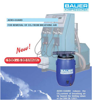 The first compressor Carbon Dioxide pre-scrubber ‘The Bauer Aeroguard’
However, why not do this with the final output filter cartridge? Well this has been tried without success, and many filters still have a 2nd section of molecular sieve AFTER the activated carbon section that is supposed to be there for this purpose (see below).
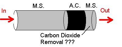
Key:- MS = Molecular sieve, AC = Activated Carbon
But there are some issues with this type of CO2 removal design.
1. Although some Molecular sieves can be used for CO2 removal. They must be kept very dry, else moisture in the incoming air will be preferentially absorbed and will displace the previously absorbed CO2 into the breathing air. That is very un-desirable and results in a very high CO2 cylinder of breathing air being pumped at the point when the filter cartridge hits its end of life.
2. The quantity of MS present in all 3 element filters designed to do this task have only a tiny amount of MS in this last CO2 absorbing element – perhaps only 100g, or less.
Mathematical analysis of the Carbon dioxide scrubber filter absorbency based on NASA measurements of Molecular sieve coefficients (see below) indicates that there is simply just not enough mass of secondary MS after the AC to remove even typical 400ppm background levels of Carbon Dioxide over the whole lifetime of a typical filter cartridge. Since MS can typically only absorb 20% of its mass in Carbon dioxide, or water for that matter. Carbon dioxide is a very heavy gas, and it clogs the MS very quickly!
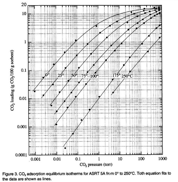
Thus If a continuous GC air analysis is done, a new filter cartridge of this type with a MS after AC CO2 removal element, it will give a nice near zero CO2 content immediately after installation, however CO2 levels will quickly rise to background levels within an hour or so of use, as the MS after AC element saturates with CO2… even when dry! A problem observed by NASA who have found that they need to continuously regenerate the MS CO2 scrubbers used on space ships several times daily.
Thus to get reliable Carbon dioxide absorbency over the normal lifetime of a typical filter cartridge would require several KG of MS after the AC – which is not practical. Thus the preferred solution is to have several Kg of rebreather scrubber chemicals receiving moist air prior to the compressor, all working at 1 bar ambient – for example, the Bauer Aeroguard , which does uses Several kilograms of traditional rebreather scrubber to achievable a CO2 filtration lifetime of a few dozen hours.
Conclusions
From the above math it is clear that both filter cartridges easily meet their manufacturers published specifications in all areas provided that:-
- The PMV is set correctly at typically 140bars – without a correctly functioning PMV removing 99.3% of all moisture in the compressed air, the actions below will be ineffectual in preventing scuba cylinder corrosion and clean dry breathing air.
- The condensate towers are purged at the manufactures recommended intervals for your ambient temperature
- The final output filter tower is changed at the correct interval for your actual measured ambient temperature.
- The background Carbon Monoxide level is less than 15ppm if you are using a simple MS/AC (Molecular Sieve/Activated Carbon) filter cartridge. You should use a filter cartridge with a Hopcalite element if your compressor is located in either a large industrial town, if you are using an internal combustion engine (Petrol or Diesel) to drive the compressor, or if the compressor is located on a boat powered by an internal combustion engine. Divers have been killed from poisonous air pumped by electrically driven compressors when the boat engine exhaust fumes have inadvertently leaked into the compressor air intake ducting.
- The compressor should be located in an area of ambient carbon dioxide levels significantly less than 500ppm, unless a carbon dioxide pre-scrubber containing several Kg of sodasorb is used.
- Molecular sieve carbon dioxide filters built into the final output filter cartridges are ineffectual at removing carbon dioxide over the entire intended life of the filter cartridge, and are of insignificant benefit.
Further thoughts
- The worlds leading diver training organizations require 3 monthly testing of a dive centers air as part of their commitment to improving dive safety. This is poorly enforced in most tropical dive destinations.
- Inline devices exist to assist the compressor operator in monitoring the filter end of life such as the Lawrence factor ‘Eyeball’ system and the advanced Bauer Securus/B-Control system that automatically shuts the compressor system down when the MS filter media reaches ‘end of life’
- Filter Math realization spreadsheet – Used to generate these results:- C ompressor_Filter_Lifetime_Calculator.xls
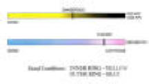
The promising Lawrence factor ‘eyeball’ device to allow the compressor operator to see if the gas contains high levels of moisture or carbon dioxide. Sadly, I have been unable to obtain any information from Lawrence factor as to the actual levels of moisture or carbon monoxide that this device reacts to. more information on monitoring SCUBA breathing air quality by colorimetry
If you would like to find out more about compressors, and achieve formal competent person status in Compressed Air Systems Maintenance Click this link Esoteric stuff and references
Deriving the intersect of MS and AC life at lower temperatures
Bauer Mariner 250, P31 filter system . MS=300g, AC=40g. Pumping rate 250L/min, 100 degree ‘C’ cylinder head temperature The AC and MS filter beds of the P31 will last 40hrs 0mins at an ambient temperature that causes a 1bar 100% RH of 14mg/m^3 Referring to Fig1 & 2, 14mg/m^3 will occur at a filter tower temperature of approx 15 degrees ‘C’, and ambient of 5 degrees ‘C’ Thus the filter MS & AC lives will simultaneously expire after 40hrs 0mins running at approx 5 degrees ‘C ambient. Closely in line with the published lower operating temperature of the Bauer Mariner 250 compressor
Coltrisub MCH16, standard filter system, MS=168g, AC=50g, Pumping rate 266L/min, 100 degree ‘C’ cylinder head temperature The AC and MS filter beds of the Coltrisub filter cartridge will last 47hrs 0mins at an ambient temperature that causes a 1bar 100% RH of 6.27mg/m^3 Referring to Fig1 & 2, 6.27mg/m^3 will occur at a filter tower temperature of approx 5 degrees ‘C’, and ambient of -5 degrees ‘C’ Thus the filter MS & AC lives will simultaneously expire after 47hrs 0mins running at approx -5 degrees ‘C’ ambient. Again, closely in line with the published lower operating temperature of the Coltrisub MCH16 compressor
A small spread sheet to calculate the 1 bar ambient pressure moisture content is given here compressor_ambient_humidity_calculator.xls
References
- (a) hse_air_quality.pdf report (b) hse_dive_equipment_report.pdf
- US Navy Diver compressed breathing air standard NAVSEA TS500-AU-SPN-010, 1-3.6.4. Diving Gases – Purity Standards
- ISO 2533 ‘Typical Composition for air http://www.iso.org/iso/iso_catalogue/catalogue_tc/catalogue_detail.htm?csnumber=7472
- Bauer Aeroguard Carbon dioxide pre-scrubber to assist in the production of EN12021 divers breathing quality air.
- Oil content in compressed air report from www.Klueber.com at an Archive of this report is contained here ==> documents/oil_content_in_compressed_air_klueber.pdf
- bauer_filter_technical_description_and_specification.pdf
- hse_moisture_levels_in_compressed_air.pdf
- Bauer P21 Filter system technical description .pdf (564Kb)
- Bauer Securus system
- NASA Document – carbon_dioxide_absorption_using_molecular_sieve.pdf

